If your subject matter experts or your audience are software engineers, using UML diagrams will help you communicate with them more effectively.
In this post, I briefly introduce UML, what technical writers gain from complementing their technical documentation with UML diagrams, and which UML diagrams I use the most.
What is UML
The Unified Modeling Language (UML) is a standard controlled by the Object Management Group (OMG). It defines a set of graphical notations and diagrams used to design software systems.
The literature classifies UML diagrams into two categories:
- Structure diagrams show the parts of a system, and how they relate to each other.
- Behaviour diagrams show how parts of a system exchange information.
Most books on UML help developers design clean object-oriented software. UML is not only a powerful modelling language, but it’s also an excellent tool for documenting existing software.
Why include UML diagrams in technical documentation
Diagrams complement your text
Diagrams add visual interest to the documentation and help readers memorize the information. You can read more on the advantages of judicious diagrams in Rüping (2009).
A two-dimensional diagram allows readers to visualize the relationships and interactions between the parts of your system at a glance; text alone does not.
UML was designed for software
The UML notation was designed to model and describe software systems; as a result, it gives you all the shapes and symbols you need to document software. It won’t help you with vendor-specific concepts such as AWS architecture diagrams, but it’s helpful for implementation-agnostic documentation. When you struggle to represent some aspect of your system, I recommend that you browse Fowler (2003) for inspiration.
UML is a standard
Because UML is a standard, developers don’t need elaborate legends to understand your diagrams. If they have to learn the UML notation, they will be able to reuse this knowledge in other teams.
Most diagramming tools support UML. I use LucidChart to draw UML diagrams at work. I love their UML sequence markup, which makes sequence diagrams easy to create and maintain.
UML diagrams I use most often
This section offers an overview of the 5 types of UML diagrams I consistently use in my technical documentation. I indicate their strengths and how I use each of them. Consult the references section for in-depth discussions on each type of UML diagram.
Use case diagram
| Quick definition | UML behaviour diagram that shows what external participants can do with the system or subsystems |
| Great for documenting | Graphical table of contents of your system’s use cases |
| Strengths | Show:
Use case diagrams are very effective when your system comprises several user interfaces that each target different groups of actors. |
| Memory Aid | 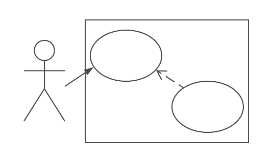 |
Components diagram
| Quick definition | UML structure diagram that shows your system’s components and how they communicate |
| Great for documenting | Architecture overviews |
| Strengths |
|
| Memory Aid | 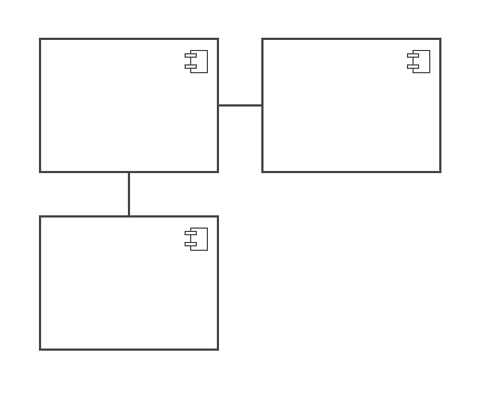 |
Activity diagram with swimlanes
Swimlanes aren’t part of the activity diagram specification, but they clarify the owners of each activity.
| Quick definition | UML behaviour diagram that represents workflows |
| Great for documenting |
|
| Strengths |
|
| Memory Aid | 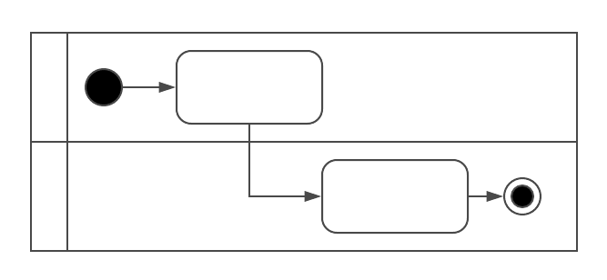 |
Sequence diagram
| Quick definition | UML behaviour diagram that shows the order in which objects or systems exchange messages to complete a use case |
| Great for documenting | The order of API calls between systems or subsystems to complete a use case |
| Strengths | Show:
|
| Memory Aid | 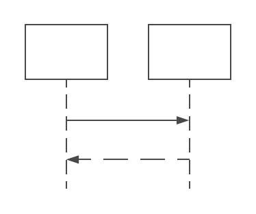 |
Class diagram
| Quick definition | UML structure diagrams that represent the objects in a system and the static relationships that exist among them |
| Great for documenting | How complex domain knowledge is modelled in your system’s object-oriented design |
| Strengths | Show the objects in your system and their relationships |
| Memory Aid |  |
Find more information
UML
- Fowler M. (2003) UML Distilled, A Brief Guide to the Standard Object Modeling Language, Third edition. Addison-Wesley Professional.
- uml-diagrams.org
- UML tutorials on the LucidChart site
Judicious diagrams in Agile documentation
Rüping A. (2009). Agile Documentation: A Pattern Guide for Producing Lightweight Documents for Software Projects. Chichester, Wiley.
